8.5. Typical Configuration
BGP
Description
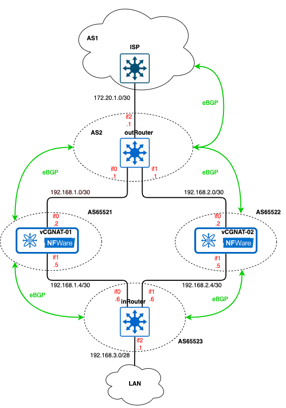
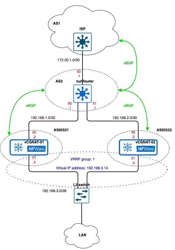
The configuration is done according to the Active/Standby mode (see the section vCGNAT Deployment Scenarios for more information), where each vCGNAT is active and ready for operation. Neighbor devices: L3 switches or routers determine which vCGNAT to use for traffic processing. Border Gateway Protocol (BGP) is used for traffic path selection. The figure below shows a simple scheme where the border router is connected to ISP. Suppose the provider advertise us default path 0.0.0.0/0 through BGP. Public AS numbers are taken as an example. Note that this simple diagram topology is intended to show the use of the vCGNAT together with the BGP routing protocol. In real case, more complex network configuration is applied with VRFs, link aggregation, and several border routers, each connected to different ISPs.
Configuration
outRouter
!
hostname outRouter
!
interface if0
 ip address 192.168.1.1/30
!
interface if1
 ip address 192.168.2.1/30
!
interface if2
 ip address 172.20.1.1/30
!
interface if3
!
interface lo
!
interface management
!
router bgp 2
 bgp log-neighbor-changes
 neighbor 172.20.1.2 remote-as 1
 neighbor 172.20.1.2 bfd
 neighbor 192.168.1.2 remote-as 65521
 neighbor 192.168.1.2 bfd
 neighbor 192.168.2.2 remote-as 65522
 neighbor 192.168.2.2 bfd
 !
 address-family ipv4 unicast
  neighbor 172.20.1.2 remove-private-AS
  neighbor 172.20.1.2 soft-reconfiguration inbound
  neighbor 172.20.1.2 prefix-list ALLOW_ALL in
  neighbor 172.20.1.2 prefix-list DENY_PRIVATE out
  neighbor 192.168.1.2 soft-reconfiguration inbound
  neighbor 192.168.1.2 prefix-list ALLOW_ALL in
  neighbor 192.168.1.2 prefix-list ALLOW_ALL out
  neighbor 192.168.2.2 soft-reconfiguration inbound
  neighbor 192.168.2.2 prefix-list ALLOW_ALL in
  neighbor 192.168.2.2 prefix-list ALLOW_ALL out
 exit-address-family
!
ip prefix-list DENY_PRIVATE seq 5 deny 192.168.0.0/16 ge 16 le 32
ip prefix-list DENY_PRIVATE seq 10 permit any
ip prefix-list ALLOW_ALL seq 5 permit any
!
end
See the section Data Interfaces to configure interfaces.
To configure neighborhood and switch on BFD (Bidirectional Forwarding Detection), use the commands
neighbor <IP-address of the neighbor router> remote-as <AS number>andneighbor <IP-address of the neighbor router> bfd.
router bgp 2
 bgp log-neighbor-changes
 neighbor 172.20.1.2 remote-as 1
 neighbor 172.20.1.2 bfd
 neighbor 192.168.1.2 remote-as 65521
 neighbor 192.168.1.2 bfd
 neighbor 192.168.2.2 remote-as 65522
 neighbor 192.168.2.2 bfd
To allow some networks to be announced to neighbors and to deny others, create rules via prefix-list. Here, two prefix-lists are applied: DENY_PRIVATE prohibits the advertisement of our private networks to the outside and allows the advertisement of others to external routers, and ALLOW_ALL allows the advertisement of the networks to our internal neighbors.
ip prefix-list DENY_PRIVATE seq 5 deny 192.168.0.0/16 ge 16 le 32
ip prefix-list DENY_PRIVATE seq 10 permit any
ip prefix-list ALLOW_ALL seq 5 permit any
To apply the prefix-lists, use the command
neighbor neighbor_IP prefix-list prefix_list_name in or out. The wordsinandoutmean applying the rule to incoming and outgoing network advertisement, respectively.
address-family ipv4 unicast
  network 172.20.1.0/30
  network 172.20.1.4/30
  neighbor 172.20.1.2 remove-private-AS
  neighbor 172.20.1.2 soft-reconfiguration inbound
  neighbor 172.20.1.2 prefix-list DENY_PRIVATE out
  neighbor 172.20.1.6 remove-private-AS
  neighbor 172.20.1.6 soft-reconfiguration inbound
  neighbor 172.20.1.6 prefix-list DENY_PRIVATE out
  neighbor 192.168.1.2 soft-reconfiguration inbound
  neighbor 192.168.1.2 prefix-list ALLOW_ALL in
  neighbor 192.168.1.2 prefix-list ALLOW_ALL out
  neighbor 192.168.2.2 soft-reconfiguration inbound
  neighbor 192.168.2.2 prefix-list ALLOW_ALL in
  neighbor 192.168.2.2 prefix-list ALLOW_ALL out
exit-address-family
!
As we do not want to advertise our private AS numbers to the Internet, we use command
neighbor neighbor_IP remove-private-asto remove them from AS-path. Please note, if the AS-path has a mix of public and private AS numbers, then the router will not remove anything.
inRouter
The inRouter will have the similar configuration except DENY_PRIVATE prefix-list:
!
hostname inRouter
!
interface if0
 ip address 192.168.1.6/30
!
interface if1
 ip address 192.168.2.6/30
!
interface if2
 ip address 192.168.3.1/28
!
interface lo
!
interface management
!
router bgp 65523
 bgp log-neighbor-changes
 neighbor 192.168.1.5 remote-as 65521
 neighbor 192.168.1.5 bfd
 neighbor 192.168.2.5 remote-as 65522
 neighbor 192.168.2.5 bfd
 !
 address-family ipv4 unicast
  network 192.168.3.0/28
  neighbor 192.168.1.5 soft-reconfiguration inbound
  neighbor 192.168.1.5 prefix-list ALLOW_ALL in
  neighbor 192.168.1.5 prefix-list ALLOW_ALL out
  neighbor 192.168.2.5 soft-reconfiguration inbound
  neighbor 192.168.2.5 prefix-list ALLOW_ALL in
  neighbor 192.168.2.5 prefix-list ALLOW_ALL out
 exit-address-family
!
ip prefix-list ALLOW_ALL seq 5 permit any
!
vCGNAT01
!
hostname vCGNAT01
!
ip route 203.0.113.0/25 Null0
!
interface if0
 ip address 192.168.1.2/30
 ip nat outside
!
interface if1
 ip address 192.168.1.5/30
 ip nat inside
!
interface if2
!
interface lo
!
interface management
!
router bgp 65521
 bgp log-neighbor-changes
 neighbor 192.168.1.1 remote-as 2
 neighbor 192.168.1.1 bfd
 neighbor 192.168.1.6 remote-as 65523
 neighbor 192.168.1.6 bfd
 !
 address-family ipv4 unicast
  network 192.168.1.0/30
  network 192.168.1.4/30
  network 203.0.113.0/25
  neighbor 192.168.1.1 soft-reconfiguration inbound
  neighbor 192.168.1.1 prefix-list ALLOW_ALL in
  neighbor 192.168.1.1 prefix-list ALLOW_ONLY out
  neighbor 192.168.1.6 soft-reconfiguration inbound
  neighbor 192.168.1.6 prefix-list ALLOW_ALL in
  neighbor 192.168.1.6 prefix-list IN_POLICY out
 exit-address-family
!
ip prefix-list ALLOW_ONLY seq 10 permit 203.0.113.0/25
ip prefix-list IN_POLICY seq 5 deny 203.0.113.0/25
ip prefix-list IN_POLICY seq 10 permit any
ip prefix-list ALLOW_ALL seq 5 permit any
!
nat pool default-pool
 range 203.0.113.1 203.0.113.127
 enable
!
nat subscriber-group default-group
 pool default-pool
!
nat rule subnet 192.168.3.0/28 subscriber-group default-group
!
end
See the section Typical Configuration to configure NAT.
The network 203.0.113.0/25 must have the exact route, otherwise it will not be added to the BGP table - this is a prerequisite. To bypass this restriction, traffic from 203.0.113.0/25 must go to Null0
ip route 203.0.113.0/25 Null0. This route means that all packets to this subnet will be discarded. However, normal operation will not be disturbed. If there are more exact routes (with a mask greater than /23), they will be preferred according to the Longest Prefix Match rule.Here we use three prefix-lists to configure network advertisement to neighbor:
ALLOW_ONLY to advertise only 203.0.113.0/25 network to the outRouter. The pool of the IP addresses from this network will be used for mapping.
IN_POLICY to deny advertisement 203.0.113.0/25 to our internal network and permit all others.
ALLOW_ALL to accept all networks from the outRouter and the inRouter.
vCGNAT02
The configuration for vCGNAT02 is almost identical:
!
hostname vCGNAT02
!
ip route 203.0.113.0/25 Null0
!
interface if0
 ip address 192.168.2.2/30
 ip nat outside
!
interface if1
 ip address 192.168.2.5/30
 ip nat inside
!
interface lo
!
interface management
!
router bgp 65522
 bgp log-neighbor-changes
 neighbor 192.168.2.1 remote-as 2
 neighbor 192.168.2.1 bfd
 neighbor 192.168.2.6 remote-as 65523
 neighbor 192.168.2.6 bfd
 !
 address-family ipv4 unicast
  network 192.168.2.0/30
  network 192.168.2.4/30
  network 203.0.113.0/25
  neighbor 192.168.2.1 soft-reconfiguration inbound
  neighbor 192.168.2.1 prefix-list ALLOW_ALL in
  neighbor 192.168.2.1 prefix-list ALLOW_ONLY out
  neighbor 192.168.2.1 route-map AS_PATH_PREP out
  neighbor 192.168.2.6 soft-reconfiguration inbound
  neighbor 192.168.2.6 prefix-list ALLOW_ALL in
  neighbor 192.168.2.6 prefix-list IN_POLICY out
  neighbor 192.168.2.6 route-map AS_PATH_PREP out
 exit-address-family
!
ip prefix-list ALLOW_ONLY seq 10 permit 203.0.113.0/25
ip prefix-list IN_POLICY seq 5 deny 203.0.113.0/25
ip prefix-list IN_POLICY seq 10 permit any
ip prefix-list ALLOW_ALL seq 5 permit any
!
route-map AS_PATH_PREP permit 10
 set as-path prepend 65522
!
nat pool default-pool
 range 203.0.113.1 203.0.113.127
 enable
!
nat subscriber-group default-group
 pool default-pool
!
nat rule subnet 192.168.3.0/28 subscriber-group default-group
!
end
except for one thing - we want all traffic to go through the vCGNAT01, and the vCGNAT02 should be in the standby mode. If something goes wrong with the vCGNAT01 or route, the traffic will go through the vCGNAT02. For that, use AS-Path prepend mechanism which will make the route through the vCGNAT02 longer by adding an extra hop:
First, create the rule AS_PATH_PREP
route-map AS_PATH_PREP permit 10and set up the as-path added by extra hoproute-map AS_PATH_PREP permit 10.Then apply this rule to the neighbors:
neighbor 192.168.2.1 route-map AS_PATH_PREP outandneighbor 192.168.2.6 route-map AS_PATH_PREP out.
Verification
To check if BGP is configured correctly and path selection works, use the following commands:
show ip bgpDisplay information about BGP routes in the BGP routing table.show ip bgp neighbors neighbor_IP advertised-routesDisplay the routes advertised to the neighbor.show ip bgp neighbors neighbor_IP received-routesDisplay the routes received from the neighbor.show ip routeDisplay the current state of the routing table. Use this command to check connectivity between all hosts on the network.
Now, if we look at what route the outRouter receives from the vCGNAT02, we will see an extra hop 65522:
outRouter# show ip bgp neighbors 192.168.2.2 received-routes
BGP table version is 4, local router ID is 192.168.2.1, vrf id 0
Default local pref 100, local AS 2
Status codes:  s suppressed, d damped, h history, * valid, > best, = multipath,
               i internal, r RIB-failure, S Stale, R Removed
Nexthop codes: @NNN nexthop's vrf id, < announce-nh-self
Origin codes:  i - IGP, e - EGP, ? - incomplete
RPKI validation codes: V valid, I invalid, N Not found

   Network          Next Hop            Metric LocPrf Weight Path
*> 203.0.113.0/25   192.168.2.2              0             0 65522 65522 i

Total number of prefixes 1
Additionally, traffic will pass through the vCGNAT01 because this route is shorter than through the vCGNAT02:
inRouter# show ip bgp neighbors 192.168.2.5 received-routes
BGP table version is 10, local router ID is 192.168.3.1, vrf id 0
Default local pref 100, local AS 65523
Status codes:  s suppressed, d damped, h history, * valid, > best, = multipath,
               i internal, r RIB-failure, S Stale, R Removed
Nexthop codes: @NNN nexthop's vrf id, < announce-nh-self
Origin codes:  i - IGP, e - EGP, ? - incomplete
RPKI validation codes: V valid, I invalid, N Not found

   Network          Next Hop            Metric LocPrf Weight Path
*> 0.0.0.0/0        192.168.2.5                            0 65522 65522 2 1 i
*> 192.168.1.0/30   192.168.2.5                            0 65522 65522 65523 65521 i
*> 192.168.1.4/30   192.168.2.5                            0 65522 65522 65523 65521 i
*> 192.168.2.0/30   192.168.2.5              0             0 65522 65522 i
*> 192.168.2.4/30   192.168.2.5              0             0 65522 65522 i
*> 192.168.3.0/28   192.168.2.5                            0 65522 65522 65523 i

Total number of prefixes 6
Make sure the ISP does not receive any private ASN and IP addresses:
ISP# show ip bgp
BGP table version is 1, local router ID is 172.20.1.2, vrf id 0
Default local pref 100, local AS 1
Status codes:  s suppressed, d damped, h history, * valid, > best, = multipath,
               i internal, r RIB-failure, S Stale, R Removed
Nexthop codes: @NNN nexthop's vrf id, < announce-nh-self
Origin codes:  i - IGP, e - EGP, ? - incomplete
RPKI validation codes: V valid, I invalid, N Not found

   Network          Next Hop            Metric LocPrf Weight Path
   0.0.0.0/0        0.0.0.0                  0         32768 i
*> 203.0.113.0/25   172.20.1.1                             0 2 i

Displayed  2 routes and 2 total paths

ISP# show ip route
Codes: K - kernel route, C - connected, S - static, R - RIP,
       O - OSPF, I - IS-IS, B - BGP, T - Table, v - VNC,
       V - VNC-Direct,
       > - selected route, * - FIB route, q - queued, r - rejected, b - backup
       t - trapped, o - offload failure

C>* 172.20.1.0/30 is directly connected, if0, 00:03:39
B>* 203.0.113.0/25 [20/0] via 172.20.1.1, if0, weight 1, 00:03:35
OSPF
Description
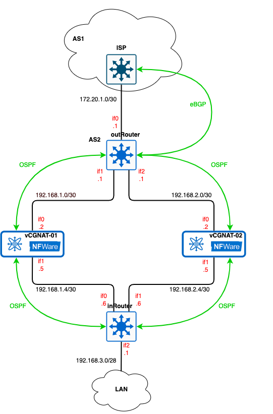
Below is the description of the routers and vCGNAT (in Active/Standby mode) configurations that intended to be performed if you use the OSPF protocol to distribute routing information throughout the internal network. Suppose the provider advertise us default path 0.0.0.0/0 through BGP. The logic design topology remains the same. BGP is used to distribute routes across the external network.
Configuration
outRouter
!
hostname outRouter
!
ip router-id 172.16.255.1
!
interface if0
 ip address 172.20.1.1/30
 ip ospf passive
!
interface if1
 ip address 192.168.1.1/30
!
interface if2
 ip address 192.168.2.1/30
 ip ospf cost 100
!
interface if3
!
interface lo
 ip address 172.16.255.1/29
!
interface management
!
router bgp 2
 bgp log-neighbor-changes
 neighbor 172.20.1.2 remote-as 1
 !
 address-family ipv4 unicast
  network 172.20.1.0/30
  network 203.0.113.0/25
  neighbor 172.20.1.2 soft-reconfiguration inbound
  neighbor 172.20.1.2 prefix-list ALLOW_ALL out
 exit-address-family
!
router ospf
 network 192.168.1.0/30 area 0
 network 192.168.2.0/30 area 0
 default-information originate
 exit
!
ip prefix-list ALLOW_ALL seq 5 permit any
See detailed instruction in the section Data Interfaces to configure interfaces.
The BGP Routing Process configuration is shown in the section BGP above. Note that since we do not use BGP internally, the public address pool
203.0.113.0/25must be announced on the border router, not vCGNAT.First, it is necessary to set the router-id. By default, it is the largest address of the loopback interfaces. We will use network 172.16.255.0/29 for that purpose.
!
ip router-id 172.16.255.1
!
interface lo
 ip address 172.16.255.1/29
!
Then, start the OSPF process on the router and announce which networks will be advertised.
router ospf
 network 192.168.1.0/30 area 0
 network 192.168.2.0/30 area 0
To forward the subscribers’ traffic to the Internet, distribute the default route throughout the internal network by the command
default-information originate.To force packets to take one route (through vCGNAT01) and disable ECMP (Equal-cost multi-path routing), increase the route’s cost to the vCGNAT02. To do this, use the command
ip ospf cost 100on the interface that looks towards the vCGNAT02. Use the same command for the inRouter.
inRouter
The configuration is simple and resembles the outRouter:
!
hostname inRouter
!
ip router-id 172.16.255.4
!
interface if0
 ip address 192.168.1.6/30
!
interface if1
 ip address 192.168.2.6/30
 ip ospf cost 100
!
interface if2
 ip address 192.168.3.1/30
!
interface lo
 ip address 172.16.255.4/29
!
interface management
!
router ospf
 network 192.168.1.4/30 area 0
 network 192.168.2.4/30 area 0
 network 192.168.3.0/30 area 0
 exit
!
vCGNAT01
!
hostname vCGNAT01
!
ip router-id 172.16.255.2
ip route 203.0.113.0/25 Null0
!
interface if0
 ip address 192.168.1.2/30
 ip nat outside
!
interface if1
 ip address 192.168.1.5/30
 ip nat inside
!
interface lo
 ip address 172.16.255.2/29
!
interface management
!
router ospf
 redistribute static
 network 192.168.1.0/30 area 0
 network 192.168.1.4/30 area 0
 exit
!
nat pool default-pool
 range 203.0.113.1 203.0.113.127
 enable
!
nat subscriber-group default-group
 pool default-pool
!
nat rule subnet 192.168.3.0/30 subscriber-group default-group
!
See the detailed instruction in Typical Configuration section to configure the NAT.
To make the internal devices know about 203.0.113.0/25 network, add a route into Null0 and enable static redistribution.
!
ip route 203.0.113.0/25 Null0
!
router ospf
 redistribute static
vCGNAT02
The configuration for the vCGNAT02 is the same with appropriate changes to the IP addresses:
!
hostname vCGNAT02
!
ip router-id 172.16.255.3
ip route 203.0.113.0/25 Null0
!
interface if0
 ip address 192.168.2.2/30
 ip nat outside
!
interface if1
 ip address 192.168.2.5/30
 ip nat inside
!
interface lo
 ip address 172.16.255.3/29
!
interface management
!
router ospf
 redistribute static
 network 192.168.2.0/30 area 0
 network 192.168.2.4/30 area 0
 exit
!
nat pool default-pool
 range 203.0.113.1 203.0.113.127
 enable
!
nat subscriber-group default-group
 pool default-pool
!
nat rule subnet 192.168.3.0/30 subscriber-group default-group
!
Verification
If everything has been done correctly, the routes, for example, on the outRouter, will look as follows:
outRouter# show ip route
Codes: K - kernel route, C - connected, S - static, R - RIP,
       O - OSPF, I - IS-IS, B - BGP, T - Table, v - VNC,
       V - VNC-Direct,
       > - selected route, * - FIB route, q - queued, r - rejected, b - backup
       t - trapped, o - offload failure

S>* 0.0.0.0/0 [1/0] via 172.20.1.2, if0, weight 1, 00:12:19
C>* 172.16.255.0/29 is directly connected, lo, 00:12:20
C>* 172.20.1.0/30 is directly connected, if0, 00:12:20
O   192.168.1.0/30 [110/10] is directly connected, if2, weight 1, 00:12:18
C>* 192.168.1.0/30 is directly connected, if2, 00:12:19
O>* 192.168.1.4/30 [110/20] via 192.168.1.2, if2, weight 1, 00:11:27
O   192.168.2.0/30 [110/100] is directly connected, if3, weight 1, 00:12:19
C>* 192.168.2.0/30 is directly connected, if3, 00:12:19
O>* 192.168.2.4/30 [110/110] via 192.168.2.2, if3, weight 1, 00:11:34
O>* 192.168.3.0/30 [110/30] via 192.168.1.2, if2, weight 1, 00:11:27
O>* 203.0.113.0/25 [110/20] via 192.168.1.2, if2, weight 1, 00:11:26
You see a default route to the ISP router and a route to the 203.0.113.0/25 network. Since we have increased the route’s cost through the vCGNAT02, only route through the vCGNAT01 got into the routing table. If the link or the vCGNAT01 goes down, a route to the 203.0.113.0/25 network via the vCGNAT02 O>* 203.0.113.0/25 [110/20] via 192.168.2.2, if2, weight 1, will be added instead.
VRRP
Description
The main idea of High Availability using VRRP is that we have active and standby vCGNATs. Active means that vCGNAT forwards both traffic from customers to the Internet and from the Internet to customers. Standby means that vCGNAT should serve all traffic in case Active vCGNAT loses its uplink or downlink connectivity.
Tracks and RTM CLI policies are used to achieve that. First, we need to track the VRRP state and number of next hops for a particular route (a default route in a typical setup). When VRRP changes its state or number of the next hops for the chosen route, RTM CLI policy kicks in and does what it is programmed for.
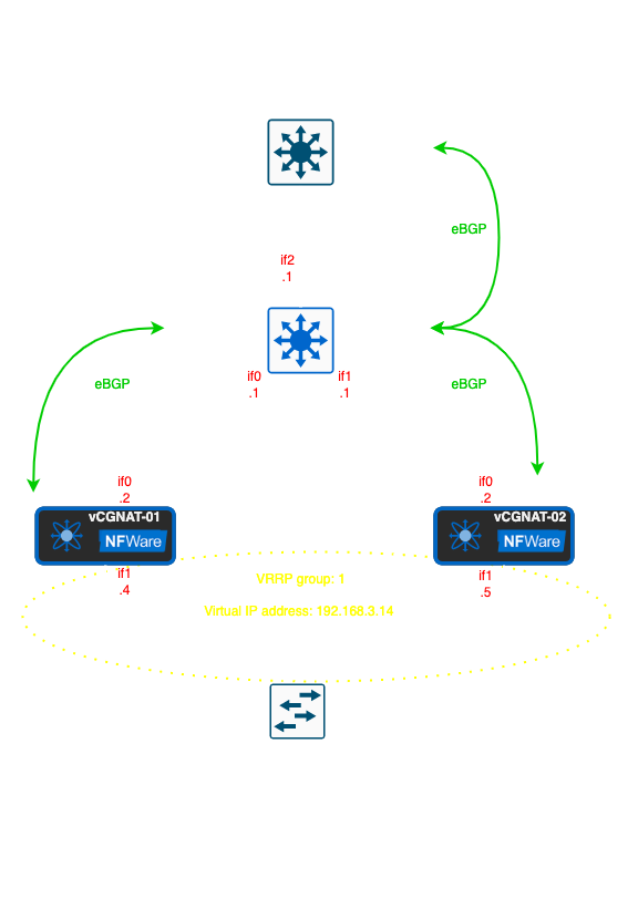
The network diagram below represents user hosts directly connected to vCGNATs through the L2 switch. The if1 interfaces of the vCGNATs, the user hosts, and the Virtual IP address are in the same network 192.168.3.0/28.
All traffic initially goes through the vCGNAT01, and the vCGNAT02 is in the standby mode. To achieve that, use AS-Path prepend mechanism which will make the route through the vCGNAT02 longer by adding an extra hop. The full configuration of the network nodes can be found in BGP section.
VRRP Configuration
The configuration is very simple: you need to set the VRID, the priority, virtual ip address and enable preempt mode:
vCGNAT01
interface if1
 ip address 192.168.3.4/28
 ip nat inside
 vrrp 1 priority 120
 vrrp 1 preempt
 vrrp 1 preempt delay minimum 60
 vrrp 1 ip 192.168.3.14
The delay vrrp 1 preempt delay minimum 60 means that the vCGNAT01 will wait for 60 seconds before becoming Master, and this delay is necessary if, for some reason, BGP is down and it needs enough time to be established and advertise the routes. But, if the session synchronization is enabled, you should take into account the time required for the sessions to be synchronizated from vCGNAT02 to vCGNAT01. The delay should be chosen so that there are as few unsynchronized sessions as possible.
The same configuration is for the vCGNAT02, but as it is a VRRP backup router, the priority will be less than 120:
vCGNAT02
interface if1
 ip address 192.168.3.5/28
 ip nat inside
 vrrp 1 priority 90
 vrrp 1 preempt
 vrrp 1 ip 192.168.3.14
Note
VRID number must be unique in your network, because Virtual MAC depends on VRID and you have to avoid the situations when VRID groups have the same Virtual MAC.
Track System Configuration
The track system configuration is applied only for the vCGNAT01:
!
track 1 vrrp 1 interface if1 ip state master
track 2 ip route 0.0.0.0/0 ecmp-number less-equal 0
!
rtm cli-policy 1
 event track 1 state positive
 action 1 cli configure terminal
 action 2 cli router bgp 65521
 action 3 cli address-family ipv4 unicast
 action 4 cli network 203.0.113.0/25
!
rtm cli-policy 2
 event track 1 state negative
 action 1 cli configure terminal
 action 2 cli router bgp 65521
 action 3 cli address-family ipv4 unicast
 action 4 cli no network 203.0.113.0/25
!
rtm cli-policy 3
 event track 2 state negative
 action 1 cli configure terminal
 action 2 cli interface if1
 action 3 cli vrrp 1 priority 120
!
rtm cli-policy 4
 event track 2 state positive
 action 1 cli configure terminal
 action 2 cli interface if1
 action 3 cli vrrp 1 priority 1
!
Conclusion
Let us explain what these policies do:
RTM cli policy 1starts announcing NAT pool to BGP when process vrrp 1 changes its state to Master.RTM cli policy 2stops announcing NAT pool to BGP when process vrrp 1 changes its state from Master to anything else.RTM cli policy 3increments VRRP priority to a normal value when the number of next hops for the default route becomes bigger than 0.RTM cli policy 4decrements VRRP priority to a lower value when the number of next hops for the default route becomes 0, which means that route is not in the RIB.
This configuration allows to avoid traffic blackhole in the following cases:
When the downlink of the Active vCGNAT01 node goes down, the VRRP state changes from Master to Down.
RTM cli policy 2triggers and withdraws advertising NAT pool network, effectively redirecting all the incoming traffic to the Backup vCGNAT02 node. When the downlink of the Active vCGNAT01 node goes up again, the VRRP state changes to Backup and then to Master, causingRTM cli policy 1to announce NAT pool network again, restoring normal traffic flow.When the uplink of the Active vCGNAT01 node goes down, the default route is removed from the RIB, which means there are no next hops for it.
RTM
cli policy 4
triggers and decrements VRRP priority, effectively redirecting all traffic from customers to the Backup vCGNAT02 node. When uplink is brought up again, the default route reappears in the RIB, andRTM cli policy 3changes VRRP priority to normal value, moving customers’ traffic to the vCGNAT01 again.When the Active vCGNAT01 node reboots, it is essential to steer traffic from inside and outside simultaneously. Otherwise, it may be blackholed for some time. After the vCGNAT01 boots, VRRP establishes the relationship first, and the vCGNAT01 waits for the preemption delay timer. When setting this timer, one should keep in mind that it must be sufficient for BGP to come up and for NAT sessions database to synchronize. While waiting, the vCGNAT01 will be in VRRP Backup state, which means that
RTM cli policy 2will not allow advertising NAT pool network to the BGP neighbors. When BGP comes up, and the vCGNAT01 receives the default route,RTM cli policy 3will trigger and set VRRP priority to normal value, but vCGNAT will still wait in the Backup state. Now, everything is ready, and when the preemption delay timer expires, the vCGNAT01 becomes VRRP Master.RTM cli policy 1triggers and announces NAT pool network to the BGP neighbors. Since that moment, all inbound and outbound traffic goes through the vCGNAT01.